VACUUM FRYING / FRYER MESIN KERIPIK BUAH

tool for Fruits & Vegetables Fry Chips
Specification Vacuum Frying

Capacity (Kg): 1.5 kg VACUUM FRYING / FRYER  MESIN KERIPIK BUAH

Rasio Kompresi Mesin

Compression ratio of engine, whether it?
The term compression machine become one in the automotive lexicon. Some argue that it shows the ratio of air pressure proportional to gasoline / fuel. True?


4 stroke engine has four action steps based on the Carnot cycle concept (Physical Science). That meet hukum2 thermodynamics. The four cycles are as follows:

1. Intake (step suction / suction stroke): exploitation of air and fuel mixture (can be derived from the carburetor or injection system)

2. Compression Stroke (step adder pressure): air and fuel mixture is compressed by the piston moving toward the top dead point (in the direction i in the figure). The best mixture according to (stochiometric) is 15:1, 15 parts of air volume and a volume of fuel (gasoline).

3. Combustion (step business / power stroke): here the mixture of fuel and compressed air that has been burned by using electric shock sparks from spark plugs. The result is a combustion and the volume of fluid / gas combustion products will expand abruptly (with a value of power) and will push the cylinder piston downward (toward the bottom dead point; in the direction G in the figure 1). And a few degrees before the piston reaches top dead point, the spark plug to ignite sparks splashed fuel - air, here the results of the combustion gas pressure will be increased by approximately 10x compared to the compression step.

4. Stroke Exhaust (Step disposal): here the rest of the combustion gases will be discharged out (to the exhaust) through the exhaust port (J).

These four processes can be described as follows:


Compression pressure is the average effective pressure that occurs in the combustion chamber just above the piston. Compression pressure was also divided by two definitions, compression pressure and compression pressure combustion motor.

Compression pressure is the pressure of this motor is often measured by the mechanical compression equipment to the units kPa gauge, psi or bar. Motor pressure finally better known as the compression pressure. This pressure reading compression pressure in the combustion chamber without ignition spark plugs, how to install compression gauge in spark plug hole and then pull the handle of the gas we fully (full open throttle) and then we crank the kick starter until the needle moves up and stops at a certain rate. Now this figure is the pressure of the compression motor.

This motor compression pressure range 900 kPa to 1400kPa for standard motors, or 9-13 psi.

The second is the pressure of the combustion chamber. This pressure is calculated when the engine starts or the combustion process occurs. This measurement does not use compression tool gauge anymore, but uses pressure sensors embedded in the cylinder head. Compression pressure combustion can achieve a 10x of motor pressure. This pressure in his end in a diagram describing the graph of P - theta (pressure versus crankshaft degrees).

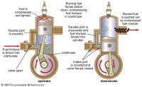
In the second machine is not only there two steps:
1. step suction (intake) and combustion take place together, at the top and bottom of the piston.
2. step flue (exhaust) and compresi done bersama2.
The second process can be described as follows:


Well, so-called compression engines or, more precisely is the engine compression ratio combustion chamber volume ratio (when the piston is at the top of top dead point above) with a total space of piston cylinder (combustion chamber and the compression space). Suppose the volume of the combustion chamber and given the name Vb is the total cylinder volume Vt, and the volume of space compression is a compression ratio of VK it could be written as

Compression ratio: (Vt) / (Vb) = (Vb + VC) / (Vb)

Suppose X is the ratio of 9.0:1 Supra engine means the ratio Vt / Vb = 9. The higher the value of Vt / Vb then the energy can be produced engines will be even greater, because the compression air is getting better. Motorcycle engines now have a greater compression ratio. Eg Jupiter MX 10,9:1, Yamaha etc. Vixion 10:4:1. The higher the compression ratio engines need fuel with higher octane rating (the more resistant high pressure before burning). 9.0:1 compression ratio down enough given the premium (with a value of RON-Research Octan Number -> 88) while the rest require pertamax 92 and above.

Source: various sources, hkuracing


Gambar Mesin 2 Langkah

2 STROKE BASIC ENGINE TUNING PHOTO . bit brief information about the two machines can not
Through this information I tried to explain in simple / short,
Gambar Mesin 2 Langkah
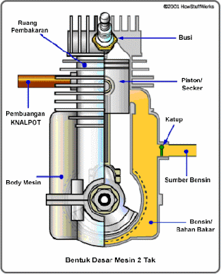
because I am not an expert on engines, seandanyai in my explanation none the less true please corrections, possibly for colleagues who understand or have a lot of experts in terms of understanding the two machines not working system (two stroke), assuming this information as additional material information for colleagues. Engine 2's structure can be seen in the picture.
Gambar Mesin 2 Langkah
Gambar Mesin 2 Langkah 2 stroke engine
Basically the two machines not working process there are two so called two no. Meaning of "No" itself means a blow (stroke).

Compression process (making direct fuel compressed)
The combustion process (direct combustion exhaust)How It Works Engine 2 do not

1. Dust collection and disposal measures
a) The piston moves from TDC to the TMB.
b) When the channel is still closed by the piston rinse, place in the vessel crank the compression of a mixture of gasoline and air.
c) Above the piston, combustion gases from previous combustion products already lost out through the exhaust channel.
d) When the channel is opened to rinse, mix gasoline with air flowing through the channel, and continue to rinse the funnel into the combustion chamber.

2. Compression and combustion steps
a) The piston moves from the TMB to the TMA.
b) rinse and dispose of closed channels, there is a compression step, and after high pressure mencapi memercikan spark plugs to burn gasoline mixed with air was
c) On the same lines are also under (in the bathtub engkolmesin) new fuel into the crankcase through the inlet.

DIAGRAM FASA (PHASE DIAGRAM)

In the process of manufacture, the required chemical composition obtained when the steel in the form of a liquid phase at high temperatures.
At the time of cooling from its melting temperature, the steel begins to change into the solid phase at a temperature of 13,500, in this phase is going on the micro structural changes. Micro structural changes can also be done by heat treatment.
When the cooling process is done slowly, it will be achieved each type of micro-balanced structure in accordance with the chemical composition and temperature of steel. Micro structural changes at various temperatures and levels of carbon can be seen in the phase diagram Balance (Equilibrium Phase Diagram).


Diagram explanation:
In the carbon content reaches 6.67% micro structure formed is called cementite Fe3C (can be seen on the far right vertical line).
Properties - properties cementitte: very hard and very brittle
On the left side of the diagram in which the carbon content is very low, at room temperature ferrite micro structure is formed.
In the steel with carbon content of 0.83%, micro structure is formed Perlit, conditions of temperature and carbon levels is called Eutectoid point.
In the steel with low carbon content up to the eutectoid point, the micro structure formed is a mixture of ferrite and pearlite.
In the steel containing eutectoid point to 6.67%, micro structure formed is a mixture of pearlite and cementite.
During cooling from melting temperature of steel with low carbon content, will form the micro structure of delta ferrite and austenite into micro structure.
In the steel with carbon content higher melting temperature falls with increasing levels of carbon, the transition from the liquid form directly into austenite.
From the diagram above we can see that in the cooling process of change - change in crystal structure and micro structure is very dependent on the chemical composition

Buku Mesin Diesel

This File contain Buku Mesin Diesel. petunjuk penggunaan Mesin Disel.
download for mesin diesel book


the triangular-bed Glashütte lathe was manufactured in the 1800s by Ernst Kreißig, a maker of watchmakers' tools from the Glashütte area near Dresden. Glashütte was not only the German centre of high-class watchmaking (and a watch-makers' school) but also home to several machine-tool builders including Karl Renner. Although Kreißig offered several versions of his lathe his later models were more conventional in appearance, resembling those from Lorch and Boley. After WW2 Kreißig was trapped inside the Russian-occupied zone and, machines from the West needing hard-to-obtain D.Marks, most of the company's output was destined for local consumption.
Although the triangular bed might be considered a trade mark signature for many makes of precision lathe from the late 1700s to the late 1800s - the most famous being Henry Maudsley's revolutionary screwcutting lathe of around 1800 - its use also extended to small lathes for watch and clock work with the original machines produced by the well-known Gustav Boley (G.Boley) being of this pattern.
Because draw-in collets retained by a threaded tube passing up a hollow headstock spindle had yet to be invented - that was a development first incorporated in the American Webster Whitcomb lathe of 1888/9 - the headstock of the Glashütte had to be designed in an ingenious way. This was accomplished by separating it into two sections with that on the left (its shape strongly reminiscent of watchmaker's "turns") supporting a 2-step pulley with the drive transmitted, through a pin and dog, to a spindle supported in the other, right-hand element. This arrangement left a length of spindle exposed along its middle section through which was cut a slot, matching one also broached through each collet's solid 5.3 mm diameter stem. To lock a collet in place a long key was passed through the slots - leaving its ends protruding from each side of the spindle - and a knurled-edge ring screwed backwards against it. Although this assembly performed perfectly it required advanced standards of engineering craftsmanship to work accurately - craftsmanship that - without the aid of yet-to-be-invented shaping, planning or grinding machines - would have involved the finest of hand-fitting skills.
An unusual attachment for the time - and one that was remarkably sophisticated and delicate in operation - was a compound slide rest. Fitted with beautifully-made horn handles this followed customary practice by using ordinary right-hand threads - so giving a "cack-handed" operation where turning the screw "inwards" caused the slide to move "out". The rest of the lathe also reflected early 19th century ideas - with even the fixed steady mimicking those used on larger lathes having a series of different diameter bevelled holes around the periphery of a disc.
The Glashütte is very rare, only one having come to light in recent years. If you have one, the writer would be interested to hear from you..
Fischer were German lathe manufacturers, based in the town of Freital in Saxonia. Inscribed on the older machine illustrated below - probably from the early 1920s - is the following legend:
Fischer & Co. Komm Ges Speczialfabric fur Drehbanke Freital i. Sa. Other pre-WW2 machines have been found with: Fischer Spezialfarbik für Drehmaschinen GmbH, Freital in Sachsen. After WW2, the town of Sachsen became part of the GDR (German Democratic Republic, the communist-controlled East Germany) and company's name was changed to VEB, a German abbreviation for Volkseigener Betrieb, the People's Enterprise.
Shown below is a Fischer lathe with a swing over the ways of approximately 15 inches and a distance between centers of 40 inches. The V-belt driven headstock incorporated a clutch with the six spindle-speeds selected by two levers, one on the front of the headstock and the other on top - the label on the headstock reading:
Scalten-nur beim Auslant


Umdr. der Arbeit ssp. pr. 1 min.
Hebel Mit Vorgelege ohne Vorgelege
Middle 26 151
Bottom 47 273
Top 84 490
A basic translation would read: Let the lathe stop before changing gear and Lever with reduction gear and without reduction gears Thus, the spindle-speed range ran from: 26, 47 and 84 r.p.m. in backgear and: 151, 273 and 490 r.p.m. in direct drive.
A conventional tumble-reverse mechanism was incorporated inside the headstock casting and below the left-hand end of the headstock spindle; it drove down to a screwcutting gearbox with outputs to a leadscrew and a powershaft for sliding and surfacing feeds.
Pictures of later Fischer lathes can be seen here.
If any reader has details of Fischer machine tools, the Fischer Company or Fischer advertising literature the writer be pleased to hear from them.

Specifications:

Manufacturer: CRAVEN (U.K.)
Capacity: 72" Swing Diam. x 48' Between Centers
Speed Range: 0.8 - 95 RPM -FULLY VARIABLE, (Solid State Control)
Threading: Inch and Metric
Leadscrew: Dual, both on front and rear
Chuck: 70", 4-Jaw chuck
Steady Rest: Yes, large 3 Stedy Rest; 2 point Follower
Motor Power: 60 HP
Machine Weight: ±120 Tons (±240 000 Lbs)

Equipped With:

* Twin Carriage, Run on Front or Back
* Rapid Traverse
* Full length Dual Threading; Leadscrews front and back
* 4 Prismatic Square Ways, (shears)
* Rebuilt Headstock at cost.........$107,000 (CAD)
* Full Solid-State Electronic VARIABLE SPEED CONTROL, Cost $32,000 (CAD)
* Motorized Tailstock
* Large box of miscellaneous goodies, not even opened

Price (FOB our warehouse, near N.Y. Border): .

116" X 14'± CMC SLIDING-GAP LATHE


Stock No: 1868

Specifications:

Manufacturer: CMC (Canada Machinery Corp., Galt, ON)
Serial No.: 6848
Swing in Gap: 116" x 76" btc (in gap)
Swing Over Bed: 64" ±
Between Centres: 14' ±
Faceplate: 76" (with slide gap grooves & bolt slot - with rim or spindle drives)
Note: Faceplate outer rim has screw adjustable back up rollers
Spindle Speeds: 8
Threading: 17 threads from 1 to 18 tpi (incl 11.5 ")
Spindle Drive: V Belt main drive to spindle through electric clutch
Electrics: 10 - 15 HP - 550V/3Ph/60Hz Belt Drive

Equipped With:
* Pendant Control, (Telemecanique push-button remote motor starter)
* Drip Central Lube to Main Gear Box
* 4 Centres
* Cutting Tools
* Change Gears, T Bolts, etc.
* Large T - slot Extension Forward from base to allow machining O.D. of
largest parts - 70" L-R X 36" F-B
* Two Compound Slide Risers

Dimensions: 180" Overall (with minimum gap length)
90" F-B (with faceplate installed)
120" Height Overall (106" Height with motor drive removed)

Price (FOB Canada, Montreal): $7,500.00 USD

Specifications:

NOTE:
This high-precision lathe is German made to the highest standards. Designed
specially for the rapid turning of extremely precise rings and disks, such as used in
jet engines and turbines of all kinds, this lathe will substantially enable the production
of all circular workpieces within its range, such as piston rings, bearings and
bearing mounts, shims, spacers, valve components, etc. up to a 1250 mm
(50" nom.) diameter.

Manufacturer Heyligenstaedt (Germany)
Model: DPN 1250

Main Dimensions
Centre Line Over Shop Floor: 72.83"
Centre Line Over Operator's Platform: 52.95"
Max. Workpiece Diameter: 49.21"
Adaptor Diameter for Clamping Discs: 59.06"
Max. Workpiece Width: 13.78"
Chuck Speeds: 2.5 - 250 RPM (infinitely variable with
cutting-speed adaptation)
Table Speed Range
No. of gear ranges: 4
Driving Power: 50 HP, plus auxiliaries

Carriages
No. of Carriages: 2
Carriage Travel: 20.47 ( Z and W axis )
Carriage Travel: 50.61 ( X and U axis )
Accuracy Both Heads
Z axis ± .0004"
X axis ± .0004"
Repeatability - Both Heads
Z axis ± .0002"
X axis ± .0002"
Feeds
Z and W Axis: 3.94 ipm
X and U Axis: 3.95 ipm
Rapid Traverses
Z- and W axis: 236.22 ipm
X- and U axis: 236.22 ipm

Automatic Tool Changer: 12 Tools, both sides

Max. workpiece weight: 10,000 lb.

Machine Weight, total: 38 tons

Design Features:

"... The chuck ring for tool accommodation has special [hydraulic pressurized]
double anti-friction bearings. The drive is effected via a helical rim gear. There is
continuous oil temperature/flow monitoring depending on revolutions. The
labyrinth packing of the main bearing includes a pressurized seal, guaranteeing the
integrity of the oil film, even down to zero revs, meanwhile totally excluding entry of
all coolant. The cross-travel bedways are parallel to each other on both sides of the
chuck and each accommodates one carriage for turning operations. Bed and carriage
slideways areprovided with fully hardened steel strips and pre-loaded rollers. ... "
-from mfr's technical design description

With excellent access from both sides of workpieces, the heavily-built, yet
compact opposed auto tool-changer turrets, enable this lathe to quickly generate all
turned pieces within its range in HALF the time of all ordinary turning centers. Even
more savings, in both precision and in total machining time,- are realized compared with
doing this kind of work on VTL's or Boring Mills. Up to four work area TV cameras
and monitors viewing the work area help the operator monitor all machining
functions in machining operations.

This lathe was part of a P & W plant closure in Connecticut, USA. It had hardly been
used at all and was well maintained. We've had it thoroughly inpsected, prior to full
re-configuring to the special needs of one of the world's top aerospace manufacturers,
and by one of U.K's top machine tool rebuilders. They are extremely happy with the
condition of our machine; their visting agents pronounced it in "superb condition" and
are now ready to fully rework this fine machine with any controls and modifications
required, while maintaining or exceeding the original performance,- to your most
exacting requirements.

PRICE, to be arranged, with chip conveyor, existing or new controls, all manuals,
complete, delivered to your factory in Europe or N. America . . . . . . £$DM¥
gambar mesin bubut

Specifications:
Max, Swing over Bed: 90"
Max. Center Distance: 52' 5" (with right end of tailstock flush to end of ways)
Faceplate: 60" 4-Jaw Chuck
Speeds: 16
Speed Range: 1.85 - 59.3 RPM (Var Speed Control added)
Controls: Push-Button Stop-Start Forward-Reverse-Jog
Threading: Full length
No. of power Feeds: 48
Feed Range: LONGITUDINAL, from .011" - .628"
CROSS, from .007" - .400"
No. of threads cut: 48 (w, 3 change gears. Others also supplied)
Threading range: From ¼ - 14 tpi (incl. 8 ½)
Spindle Bore: 2-3/4"
Steady Rests: Yes, Roller type: 66" Ø
50" Ø
30" Ø

Carriages: Heavy Duty, with Factory risers, central pressure
lube aprons, and with 4 side Toolblock clamping, on top
compound, on graduated swivel risers, mounted on main
crosslides. Motorized Rapid traverse on front of apron.
Tailstock: Offset geared-feed type for ease of use
Quill size: # 7 Morse Taper
Offset travel: Cross travel offsets up to 7" (for long tapers)
Live Center: Yes (almost new)

Construction: HEADSTOCK: standard countershaft type layout. Main
gearbox with Quick-Change selection of Feeds, Speeds and
Threads; Full motorized lubrication to main bearings,
gearbox etc. Full length leadscrew has take-up adjustments
for play etc.
BED: Two piece: 10" W. Flat ways, some scoring, but
easily re-surfaced.
Main Motor: 40 HP 3 Ph @ 875 RPM (larger easily fitted)
Dimensions: 64'6" (on floor) + cable recoiling reel
109" High + Levelling jacks (up to 7" extra if needed)
Weight: 35 - 40 Tons (est.)

Lathe is Equipped with:

* Rapid traverse
* Full-length threading to very large pitches
* Two piece bed & lead screw for ease of shipping & assembly
* No pits
* 3 Large Roller Steady Rests
* 60" 4-Jaw chuck / Faceplate
* Large & Heavy Duty

NOTE: JOHN BERTRAM & Sons, Ontario, built larger, heavy-duty and precise
machine tools until the 1960's. Parts are still available. Many major American machine
tool names of the mid-twentieth century were also built in Canada, and in many Bertram
versions, they were IMPROVED on the original design. Examples are Niles-Bertram,
Cincinnati-Bertram & Acme-Bertram etc. In MOST CASES, the BERTRAM version
was better built, often because the improvements were not yet incorporated into the
original American design.

Price: . . . . . . . . . . . . . CALL

Lathe is a process that pemakanan workpiece sayatannya done by rotating the workpiece and then imposed on the chisel driven by translation parallel to the axis of rotation of the workpiece. Swivel movement of the workpiece is cut relative motion and move the translational motion of the chisel called bait.

By setting the ratio of the workpiece rotational speed and the speed of translational chisels to get some kind of screw with different sizes ranging. This can be done by way switch gear that connects the axis translation spindel the screw axis.

Exchanger gears provided specifically to meet the needs of manufacturing the screw. The number of teeth on each cog swapper size varies from the amount of up to 15 maximum number of 127 teeth. Exchanger gears with the number 127 has a specificity that is used for conversion from metric to a threaded screw inches.

[edit] The principle of lathe work
Lathes that use a belt at the Hagley Museum

Spindel axis of the workpiece will rotate through the carrier plate so that the gears rotate on its axis spindel. Through liaison gears, rotation will be communicated to the screw shaft gear. By clamp threaded, screw shaft rotation is converted into translational motion on the sled that carries a chisel. As a result the workpiece will be screw-shaped incision.

[edit] The parts of a lathe

Lathe machine consists of a table and his head still. At the head still have the wheels spin gear changers who will play spindel axis. Axis spindel will menmutar workpiece through gallant. Main sledge will move along the table with a sledge and sleigh on the latitude and chisel holder. The main source of all those moving from an electric motor to rotate through belt PULLEY.

[edit] Types of Lathe Machine

1. Universal Lathe Machine 2. Special Lathe Machine 3. Conventional Lathe Machine 4. Lathe Machine with Computer (CNC

Gambar MESIN Colt diesel 125 ps

Specification of Mesin engine Colt Diesel, high Performance, stabil and strong motor engine. check out the photo

gambar engine colt diesel 125


SOurce :http://truckmitsubishi.blogspot.com


Specification of mesin Fuso engine all include in the picture, in the photo : engine valve photo, cylinder range
gambar mesin tronton

Spesifikasi mesin tronton 6 x2, engine big motor , tronton engine, full specification in the picture
g
Gambar mesin, specification engine tronton, buldozer , big engine car


source:http://truckmitsubishi.blogspot.com
GAMBAR ROTOR
Copper Shines in Motor Rotors. A cutaway view of a Siemens motor equipped with a copper rotor. A point to note is that the motor lacks a fan. The cooler-running copper-rotor models don’t need one, thus eliminating losses from windage. A cutaway view of the rotor itself is at right.
Avoiding Design Problems with Geometric Dimensioning and Tolerancing


GD&T is part of a larger effort, a product-development process (PDP). Some companies may not even realize they have such a thing. But they do execute a series of steps in the process of developing a new product and bringing it to market. Usually, the more complex the product, the more defined the PDP.gambar Geometric Dimensioning


A PDP serves many purposes. First, it defines a series of activities that translate new-product concepts into customer requirements that drive engineering designs and testing. Second, a PDP distributes and harmonizes activities between different departments (marketing, purchasing, engineering/design and manufacturing). Third, a PDP provides a plan for all these activities.

The Myths of GD&T
One of the interesting things about working with companies of all types is seeing how people try to blame GD&T for problems at their organizations. Here are some of the more common myths surrounding GD&T:

Myth: We don’t need GD&T because our drawings are good enough without it. Reality: Without GD&T you cannot accurately create tolerance stacks. You cannot accurately inspect your parts. The dimensioning cannot represent the product requirements.

Myth: GD&T is confusing — everyone has a different interpretation. Reality: There is a kernel of truth in the statement, but it is not the fault of the language. Incomplete or poor tolerancing on drawings is subject to more than one interpretation. Untrained drawing users may feel there are multiple interpretations. Proper drawings and a skilled workforce can greatly reduce this problem.

Myth: It takes longer to apply GD&T and we don’t have the time. Reality: If your engineers have the right skill set, it is quicker to specify symbols in place of lengthy notes.

Myth: Our suppliers don’t understand GD&T so we don’t use it. Reality: Why would you change your drawings to have less tolerance and be less clear to accommodate unskilled suppliers? Would you stop using e-mail or solid models if your suppliers didn’t have these capabilities? The use of these technologies became requirements for suppliers. GD&T has been around for many years. Require your suppliers to understand drawings.

Myth: Using GD&T raises part costs. Reality: When properly specified, GD&T has a number of tools that provide larger tolerances to reduce part-manufacturing costs. To name just a few: Round tolerance zones, Bonus tolerance, Rule #1, Composite tolerances, Functional dimensioning, Separate requirements.

Myth: With solid models, I don’t need GD&T. Reality: This may become true someday, but for now, we still need tolerances to functionally describe part features, allow maximum tolerances, analyze new designs, analyze production or field problems, and to inspect parts.

In short, a good PDP reduces the time it takes to deliver a quality product to market. So it is useful to review the role GD&T plays within a PDP. A typical PDP consist of the following stages:

• Requirements setting
• System/conceptual design
• Component/detailed design
• Manufacturing design
• Component validation
• System validation
• Manufacturing validation
• Production

Gambar BLOK MESIN Mercedez bens


This is pictures of inside engine of motor and car engine system
Almost every new car is equipped with Central Lock system. Simply lock the door from a door, the door that locks the other will follow, as well as time to unlock the door. Development of the Central Lock System is combined with a remote control as a controller of a remote door locking, or often referred to with the Keyless Entry. Also added module Alarm System that integrates with the already generally Controlnya Remote. That all these functions is to facilitate and enhance our comfort in driving.

Component that is generally used on the Remote Control System + Alarm + Central Door Lock System.

. [Www.saft7.com - and sharing automotive tips]
NOT PAKAI CENTRAL LOCK SYSTEM?

The door of your car not equipped Central Lock System? Can attach itself, kok.
In the market, generally a set of Central Lock System for sale 120ribu - 150ribu depending on brand and model.
Which generally includes, among others, as follows:

1 cable set for 4 door
4 bar (rod) drawer / booster
4 rod holder Lock Actuator
1 unit Central Lock Module
1 set screw, bolt, etc..

. [Www.saft7.com - and sharing automotive tips]
Lock Actuator

Lock Actuator is a mechanical drawer / booster. This component that will attract / encourage lever door lock. Lock Actuator is controlled by Central Lock Module.

Lock Actuator, if damaged, can be purchased with a price around 30ribu - 35ribu rupiah.
Lock Actuator have 2 types:
Main Lock Actuator

Generally, the cable has 5: Green, Blue, Brown, White & Black.
As aktuator addition, this component also functions as the regulator, so when we lock the door with a lock knob with your hands, then aktuator this will give information to the Central Lock Module for Lock Actuator also set the other to move the same.
Additional Lock Actuator:

Generally have only 2 cables: Green and Blue.
Used for doors or close the gas tank.

.

Lock Actuator generally sold in the market strength and distance of movement that is almost the same, namely the strength of push / pull of 32N (+ / - 4n) and the movement distance of 18mm (+ / - 1mm)

How the Lock Actuator is to connect the stem (rod) with rod (rod) / lever lock on each door. Each model car has a design lever / rod (rod) that is different, so please customized installation techniques with the design of the existing construction.
So also with Lock Actuator placement on the door frame.

. [Www.saft7.com - and sharing automotive tips]
Central Lock Module

Central Lock Module is the main unit set / control the entire Lock Actuator. Contains a series of electronic equipment, which set the Lock Actuator only work (given the power voltage), only about 1-2detik only to open or close. This is useful to prevent damage to / terbakarnya motor that is in the Lock Actuator.

Central Lock Module if damaged, can be purchased for around a 30ribu-50ribu rupiah